


Challenges of Specifying LIDT for CW Lasers
Usage circumstances affect continuous wave (CW) laser damage threshold more than they do pulsed laser systems, so CW laser system users need to exercise more caution. Damage threshold for CW lasers is normally specified as a measured linear power density at a given wavelength. Users should not rely too heavily on the specified CW damage threshold of an optical component without first considering the many parameters that can change the value: laser power, beam diameter, and ambient testing conditions, among others.
Definitions & Differences:
The ISO standard defines laser-induced damage threshold (LIDT) as the “highest quantity of laser radiation incident upon the optical component for which the extrapolated probability of damage is zero”.¹ Pulsed and CW lasers differ in the way they operate and, therefore, display different mechanisms of damage. Pulsed LIDT is tested by single-shot or multi-shot tests, whereas CW LIDT is tested by exposing an optic to the laser’s constant fluence for a certain amount of time. Pulsed laser damage, measured by exposure time in the nanosecond to femtosecond range, usually results from the electric field or mechanical stress damage. (More information can be found in Table 1 of our application note: Understanding and Specifying LIDT of Laser Components). Pulse durations greater than 100 picoseconds often lead to conventional melting. CW laser damage is caused by a heating or mechanical failure due to thermally-induced stress in the optic. Consequently, quasi-CW laser damage, where the exposure time is in microseconds, is caused by a combination of electric field and thermal damage.
Unique Challenges of Specifying and Testing CW LIDT
Damage threshold testing with CW lasers poses challenges that are not present in pulsed laser damage testing. Some major parameters to consider for CW testing include exposure time, beam diameter, the material of construction, defects on the sample, and mounting choice. Ambient conditions should also be taken into consideration, particularly any airflow over the optic.
Exposure time is the interval for which the optic in consideration is subjected to the laser’s power. Exposure times for CW laser damage testing are greater than one second but commonly five seconds to one minute per test site, or until the sample fails.² Another consideration related to exposure time is the amount of rest time between each test. If the sample is not given adequate time to thermally “relax,” the next exposure will be more difficult on the sample than the last. This is somewhat relatable to pulsed laser repetition rate, though on a longer timescale. This provides more uncertainty in the real world; how much time will the user give the optic to recover? This rest time can quite literally make or break the optic.
The number of defects the beam will interact with will be determined by the beam diameter chosen for testing. Understanding any imperfections on or below the surface of the optic is important. Defects can be subsurface damages like cracks or grooves, or they could be imperfections to the surface such as defects to the coating or contaminants on the optic. Coating damage usually results from facilitated absorption by dust or scratches on the surface. Sufficient energy absorption at the surface can cause delamination of the coating.² Essentially, the more defects the beam encounters, the lower the damage threshold will be.
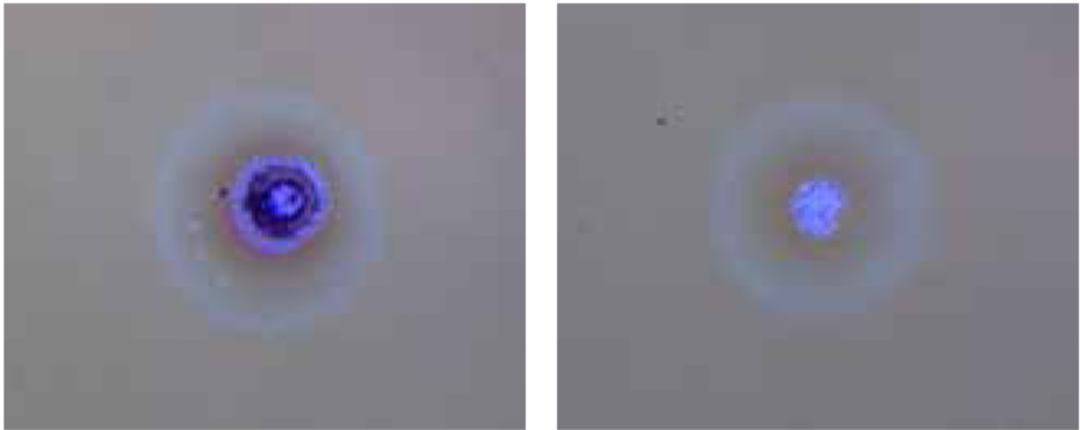
Figure 1: Various morphologies of laser-induced damage resulting from different root causes.
The thermal conductivity and absorption of the substrate material determine the profile in which the heat is distributed throughout the optic. For example, silicon and germanium transmissive optics pass infrared (IR) light but do not pass visible light, which causes absorption on the first surface.³ This first surface absorption then causes the temperature on the surface of the optic to rise which, in turn, causes a substantial temperature gradient. The size of the temperature gradient can determine whether there will be damage to the sample or not. Consequently, optics with highly-reflective coatings are often used during CW laser testing because of their ability to reflect some of the heat away from the optic.
The manner in which the sample is mounted is another significant parameter to consider. Sometimes mechanical strain can be introduced by the mount, which can increase the effects of thermal strain from laser absorption. Whether or not the sample is mounted with glue also affects how heat transfers throughout the optic. Additionally, the mounting choice introduces the possibility of cooling by convection as a result of air-flow over the sample. The presence of a heat sink and how effectively it absorbs the radiation coming off the optic can considerably increase the damage threshold of the sample.
Scaling CW Damage Threshold:
A study by Slinker, et al. (2019), correlates CW laser-induced damage directly to the optical surface’s temperature rise at the center of the beam due to absorption. For quasi-CW and CW laser systems, the heat diffusion equation is capable of predicting and scaling LIDT. Two cases are considered when modeling the damage threshold of highly reflective optics: flood illumination and spot illumination.⁴
Flood illumination is considered a large illumination area of a thin, reflective optic with a detector mounted to a heat sink. Spot illumination is a small illumination area relative to the thickness of a free-standing, reflective optic.⁴
If convection and radiation are ignored at each surface, the temperature rise on the surface at the center of the beam, over time $ \left( \small{t} \right) $, can be determined by:⁴
Characteristic time:
Where $ \small{T_0} $ is the initial temperature of the sample, $ \small{\alpha} $ is the fractional absorptance at the irradiation wavelength, $ \small{\phi} $ is the linear power density, $ \small{k} $ is thermal conductivity of the substrate, $ \small{\rho} $ is sample density, $ \small{r} $ is the radius of the sample, and $ \small{c_p} $ is the specific heat capacity $\left[ \tfrac{\text{J}}{\text{g K}} \right] $.
Damage threshold tells us the likelihood that the optic will fail under a certain amount of laser radiation. For CW lasers, this threshold can be considered a linear power density, $ \small{\phi_{DT}} \left[ \tfrac{\text{W}}{\text{cm}} \right] $, which has been proven to decrease as exposure time increases. When environmental considerations are ignored, the minimum value of linear power density as a function of exposure time can be solved by setting $ \small{T} $ equal to failure or critical temperature $ \small{T_c} $, and solving for $ \small{\phi} $:⁴
Under these conditions, the laser power required to damage the sample is a constant linear power density. Additionally, ISO standard instructs scaling in linear power density rather than in irradiance.⁴
Alternatively, taking ambient testing conditions into consideration, for a free-standing reflective optic, the temperature rise on the surface over time $\left( \small{t} \right)$ is:⁴
Characteristic time:
Where $ \small{T_0} $ is the initial temperature of the sample, $ \small{T_{\text{Air}}} $ is the temperature of the air surrounding the sample, $ \small{L} $ is sample thickness, $ \small{I} $ is irradiance $ \left[ \tfrac{\text{W}}{\text{cm} ^2} \right] $, $ \small{\alpha} $ is the fractional absorptance at the irradiation wavelength, and $ \small{t} $ is exposure time. In both equations above, $ \small{h_{\text{eff}}}$ is the effective convection coefficient – the sum of the contributions from convection and radiation. This coefficient is doubled to account for both surfaces of the sample.
Still keeping ambient conditions in mind, where there is significant air flow over the optic and radiation from the surface of the optic, the damage threshold irradiance can be calculated by:⁴
This damage threshold irradiance decreases down to a minimum value:⁴
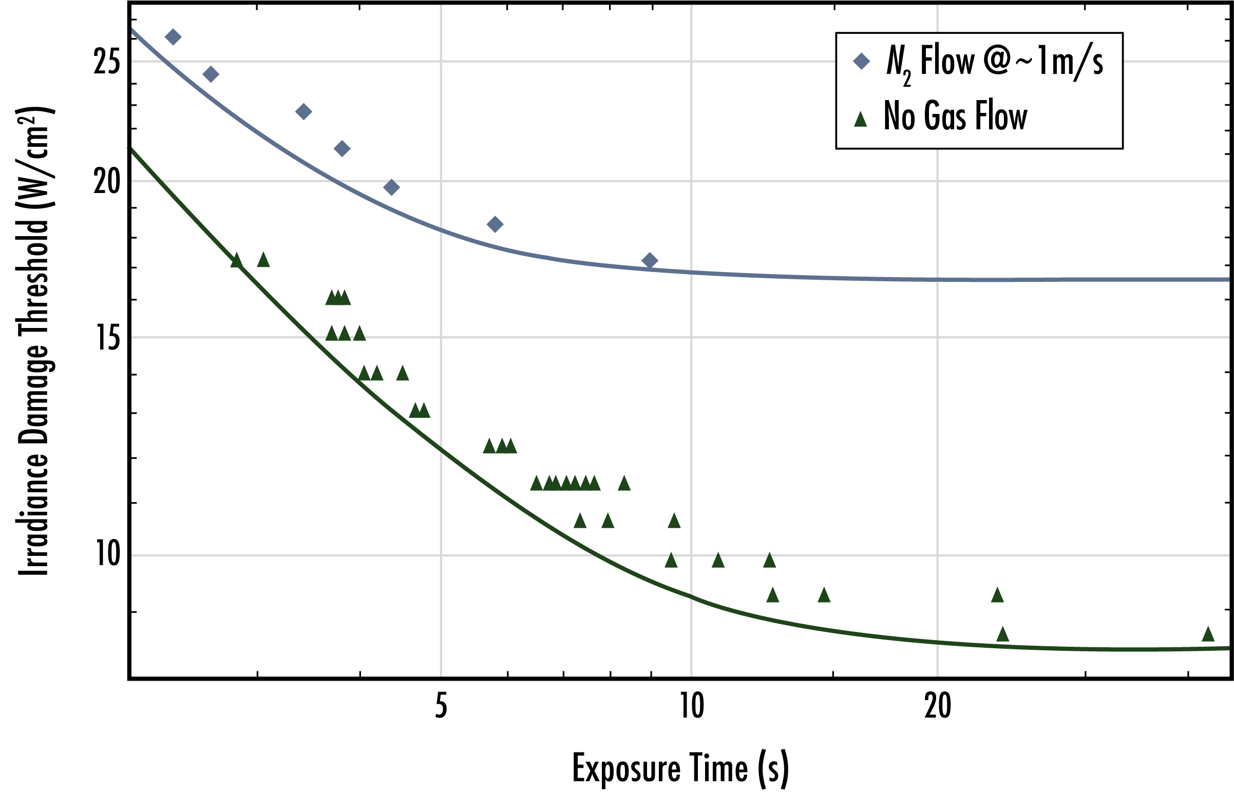
Figure 2: Irradiance scaled with increasing exposure time, under two testing conditions – ultimately displaying the effect of air flow over the sample during testing.4
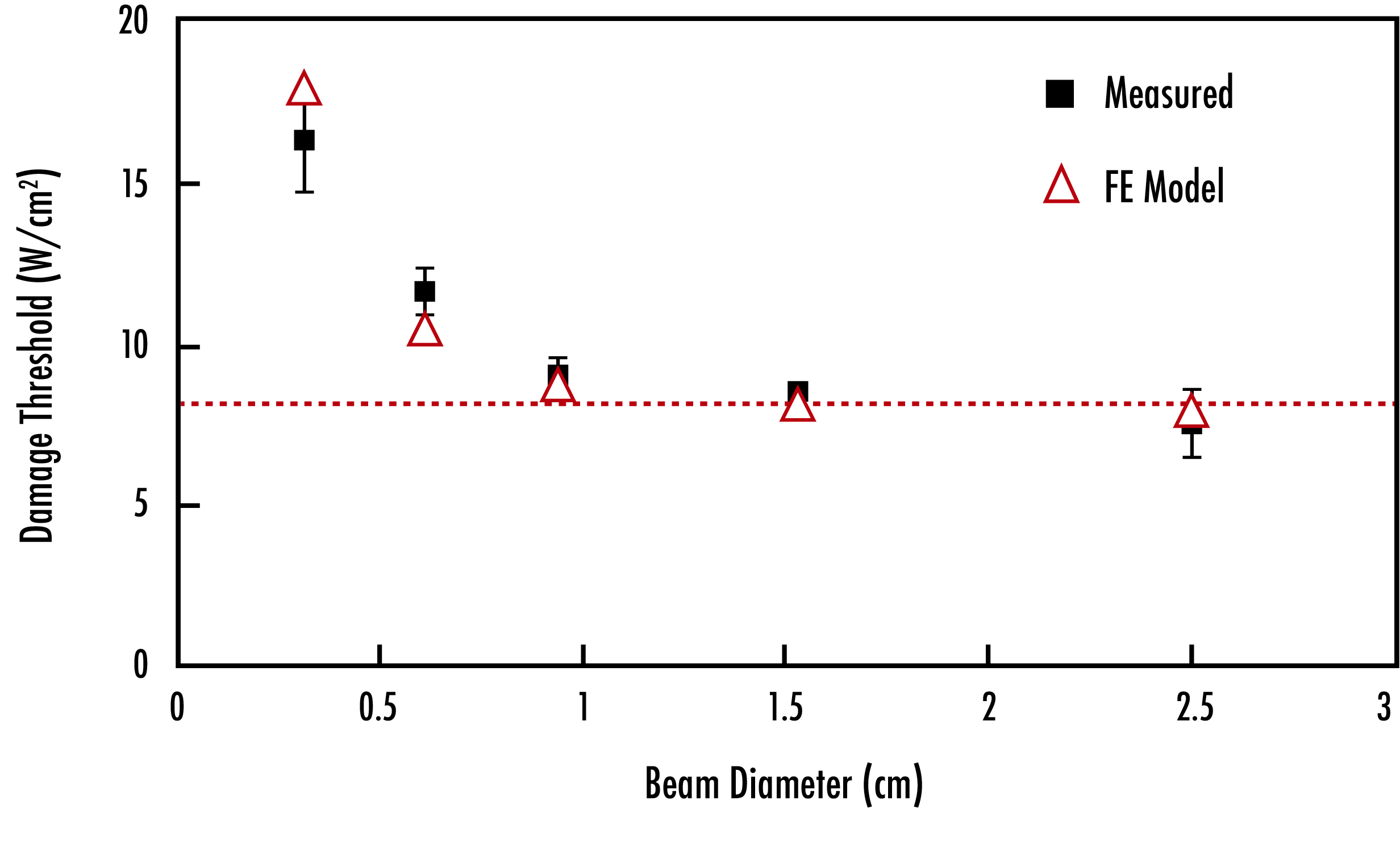
Figure 3: Damage threshold of samples exposed to quasi-CW and CW lasers decreases as beam diameter and exposure time increase.
Conclusion
For all beam diameters considered, the damage threshold of samples exposed to quasi-CW and CW lasers decreases with increased beam diameter and exposure time. The larger the beam, the more likely it is to encounter multiple defects on the optic, thus lowering the damage threshold. The way heat disperses through the sample depends on the dimensions and heat capacity of the substrate being used. Under conditions where there is high-speed airflow over the sample, the temperature on the surface of the optic is greatly reduced and therefore, the damage threshold is much higher than an uncooled optic.
The most difficult part of specifying LIDT for CW laser systems is testing samples under reproducible conditions. Various applications call for different laser powers, beam diameters, and other useful parameters, and not every user will be able to recreate the environment under which the optic was tested. Mounting, rest time, ambient conditions, and several other parameters can alter the damage threshold of an optic. The variety of testing conditions mentioned in this application note drive the challenges of specifying CW LIDT.
References
- Lasers and laser-related equipment — Test methods for laser-induced damage threshold — Part 1: Definitions and general principles. (n.d.). Retrieved December 14, 2020, from https://www.iso.org/obp/ui/
- Palmer, J. R. (1983). Continuous Wave Laser Damage on Optical Components. Optical Engineering, 22(4), 435-446.
- Palmer, J. R. (1989). Thermal Shock: Catastrophic Damage To Transmissive Optical Components In High Power Continuous Wave And Repetitive Pulsed Laser Environment. Proceedings of SPIE, 1047, 87-140.
- Slinker, K., Pitz, J., Sihn, S., & Vernon, J. P. (2019). Determining and scaling continuous-wave, laser-induced damage thresholds of thin reflectors. Optics Express, 27(4), 4748-4757.
More Resources
- Understanding and Specifying LIDT of Laser Components
- Laser Damage Threshold Testing Application Note
- Uncertainty in LIDT Specifications Application Note
- Different Types of LIDT Specifications Application Note
- Bulk Laser Damage in Glass Application Note
- Importance of Beam Diameter on Laser Damage Threshold Application Note
- LIDT for Ultrafast Lasers Application Note
- Why Laser Damage Testing is Critical for UV Laser Applications Application Note
- Metrology for Laser Optics Application Note
- Key Parameters of a Laser System Application Note
- Laser Optics Lab Video Series
or view regional numbers
QUOTE TOOL
enter stock numbers to begin
Copyright 2023, Edmund Optics Inc., 101 East Gloucester Pike, Barrington, NJ 08007-1380 USA
California Consumer Privacy Acts (CCPA): Do Not Sell or Share My Personal Information
California Transparency in Supply Chains Act
This content may include material that has been generated or modified using artificial intelligence (AI).
The FUTURE Depends On Optics®