


Chromatically Corrected F-Theta Lenses for Ultrafast Laser Applications
Authors: Vedant Agrawal, Jay Small
Table of Contents
F-theta lenses are essential components in laser scanning systems, enabling high-speed precision applications such as micromachining, additive manufacturing, and medical imaging. They maintain a flat field (image plane) while scanning, ensuring that the focused laser spot moves predictably and linearly with the scan angle. When paired with ultrafast lasers, these systems can achieve significantly smaller heat-affected zones, resulting in reduced material loss and enhanced precision. However, designing f-theta lenses for ultrafast applications requires considering various optical phenomena. Some factors, like f-theta tolerance, field flatness, and back reflections, are common across systems, while others, such as chromatic aberrations and dispersion effects, are unique to ultrafast lasers. This document explores all these factors in detail to provide a practical guide for engineers and designers. The considerations covered here were employed by Edmund Optics® in the design of our own Color Corrected F-Theta Lenses.
Fundamentals of F-Theta Lenses
F-Theta Tolerance
A unique property of an f-theta lens is that the displacement of the laser spot is linearly proportional to the angle of the incoming beam, meaning each degree of mirror movement produces a consistent, proportional shift across the scanning field. This differs from traditional lenses, where spot displacement follows a tangent relationship (Figure 1). That nonlinear behavior causes uneven processing speeds due to complex real-time calculations and often results in distorted images at the edges of the scan field. F-theta lenses eliminate these issues through their inherent linear design, ensuring uniform spot placement without software correction. [1]

However, this design introduces barrel distortion, where straight lines may appear slightly curved or bulged. Fortunately, most modern scanning systems include software compensation to correct for such distortions.[2] The term f-theta tolerance refers to the allowable deviation from the ideal linear relationship between the scan angle and the spot position. The acceptable tolerance level depends on whether the scanner system applies distortion compensation. For systems without compensation, the typical tolerance is less than 0.15%, whereas systems with built-in compensation can accommodate tolerances up to 0.50% without impacting performance.
Field Flatness
Field flatness describes how level the target surface must be for an f-theta lens to maintain proper focus across the entire scan area. Two key factors influence this: acceptance aperture and focal length. The acceptance aperture is the usable entrance pupil area of the lens through which the laser beam can pass. It determines the maximum diameter of an input beam that should enter the lens, usually mechanically restricted by an external aperture such as a scanner module. A larger beam diameter results in a smaller beam waist (the narrowest point of the focused beam). However, a smaller beam waist also reduces the Rayleigh range, the distance over which the beam remains sufficiently focused. In short, a larger acceptance aperture leads to tighter focusing, but a shorter usable range (Figure 2).
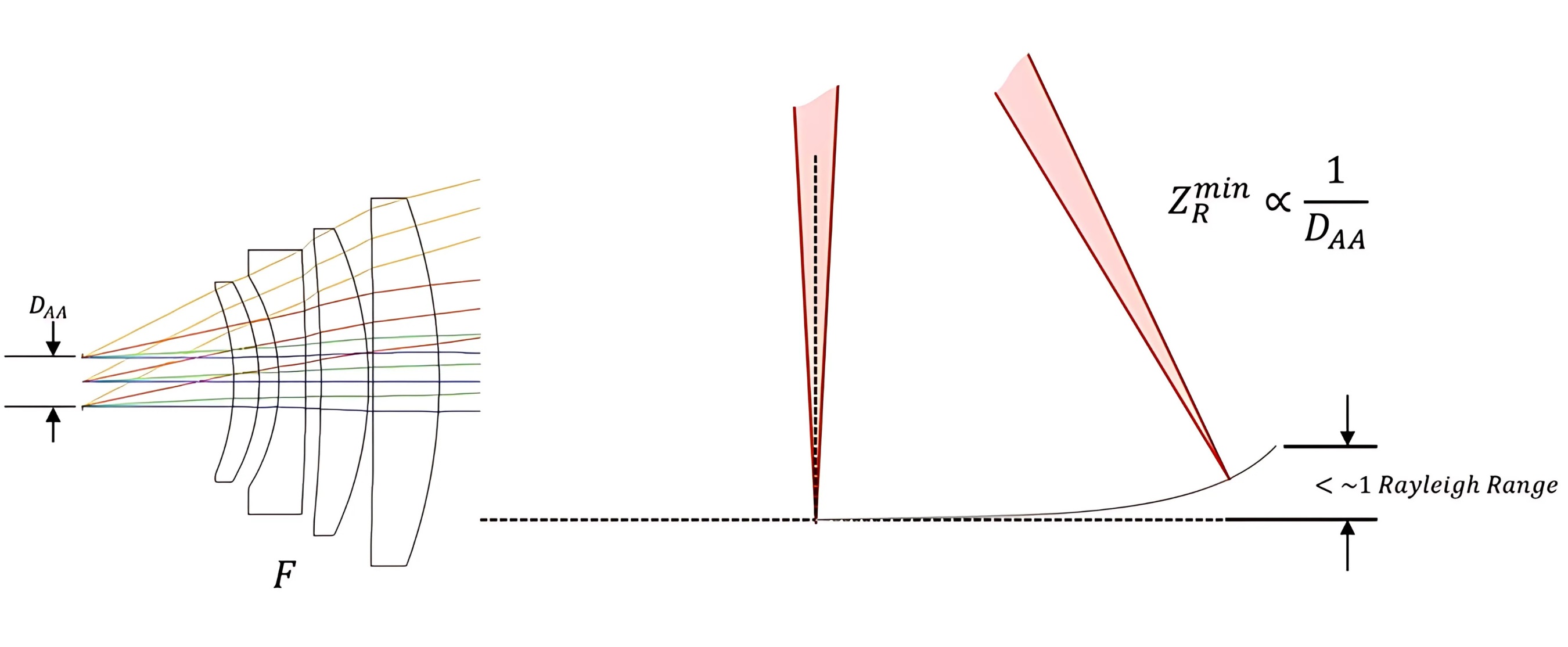
On the other hand, the focal length works in the opposite direction. A longer focal length produces a larger beam waist, which increases the Rayleigh range. This means the beam remains focused over a greater distance, making it more forgiving to surface variations. Therefore, Rayleigh range is directly proportional to focal length and inversely affected by beam diameter.
Together, these two factors determine how flat the target surface needs to be. If the surface falls outside the Rayleigh range, the beam begins to defocus, which can reduce processing accuracy and efficiency. Designing within the appropriate parameters ensures optimal performance across the full field.
Back-Reflection
When the laser beam is emitted and directed toward a target or through optical elements, some of the light is inevitably reflected backward due to the reflective properties of surfaces and interfaces. These potentially harmful reflections occur from lens element surfaces reflecting a small fraction of forward light that travels backward toward the source. Concave element surfaces—even on positive elements—can bring the back reflection to a focus. Even with high-quality anti-reflective coatings, these back reflections at a focus can damage the coatings or material due to high-intensity laser light. Therefore, these foci should avoid the surface and bulk material of the remaining lens elements. Additionally, the design should avoid foci at the scan mirror locations. However, this is challenging because their positions vary between manufacturers, and many do not openly disclose this relevant information. Other back reflection paths could potentially collimate the reverse-going light and retrace the original beam path back to the laser source. These back reflection types do not harm the lens or scanner but could potentially destabilize the laser itself.
Drivers Unique to Ultrafast Laser Scanner Systems
To understand the key drivers for designing an ultrafast laser scanning system, we must first grasp some unique concepts, such as pulse propagation within these lasers. Ultrafast lasers emit light in extremely brief pulses—lasting picoseconds or even femtoseconds. These pulses can be thought of as the precisely coordinated constructive interference of a wide spectrum of frequencies (each moving at the speed of light) that temporarily align to form an extremely short burst of light. This process is illustrated by Figure 3.

However, over time, because of the pulse’s wide spectral content, these wavelengths start to go out of phase, causing destructive interference. This introduces a fundamental lag between the pulse envelope (the region where total constructive interference occurs) and the constituent waves that form the pulse. This lag is known as group delay.
Due to the broad bandwidth and unique behavior of ultrafast pulses, specific types of optical aberrations—such as chromatic aberrations, group delay (GD), and group delay dispersion (GDD)—become critical design considerations for laser scanning systems.
Chromatic Aberrations in Ultrafast Laser Systems
Ultrafast lasers inherently possess broad spectral bandwidths, which significantly intensify chromatic aberrations in optical systems. These aberrations manifest in two primary forms: lateral (transverse) and axial (longitudinal) chromatic aberrations. Due to the high precision required in ultrafast laser scanning systems, even minor aberrations can cause substantial degradation in performance. Moreover, pre-chirping cannot correct for spatial distortions caused by chromatic aberrations.
Lateral Chromatic Aberration
Lateral chromatic aberration occurs when different wavelengths within the ultrafast pulse focus at varying radial distances from the optical axis. For example, shorter wavelengths (e.g., 1000 nm) may converge closer to the center, while longer wavelengths (e.g., 1060 nm) may focus farther from the center. This radial separation causes the focal spot to stretch or smear into an elongated shape (Figure 4), reducing both peak intensity and spatial resolution.
Importantly, pre-chirping, which adjusts the relative timing of wavelengths to correct for temporal dispersion, does not address this spatial distortion. It cannot alter the physical positions where individual wavelengths come to focus, making it ineffective for mitigating lateral chromatic aberrations.
Axial Chromatic Aberration
Axial chromatic aberration, on the other hand, arises when different wavelengths focus at varying depths along the optical axis. Due to differences in refractive index, shorter wavelengths typically focus closer to the lens, while longer wavelengths focus farther away (Figure 5). This results in a spread-out, blurred focal region that compromises resolution and energy concentration.
Again, pre-chirping is ineffective in correcting this issue. While it can alter the timing of wavelength arrival, it cannot realign the axial focal positions of the different wavelengths. By the time the pulse reaches the focus, some wavelength components may already be out of focus.
To mitigate these chromatic aberrations, optical designers often use paired optical elements with opposing dispersion properties to cancel out the net aberration. For instance, combining lenses made from materials with different dispersion characteristics can reduce both lateral and axial chromatic effects. However, this strategy can increase system complexity and raise the likelihood of back-reflections, which are undesirable in high-precision ultrafast laser scanner systems.
Group Delay
Group delay (GD) refers to the delay of the pulse envelope relative to the phase velocity of its constituent frequency components. While each individual wavelength in the spectrum travels at the speed of light, the pulse envelope (or pulse group) travels at a slightly slower velocity. This mismatch causes the constituent frequencies to fall out of sync with the envelope over time, leading to a lag as represented by Figure 6. The larger the spectral bandwidth, the more pronounced this delay becomes. GD, though less commonly discussed than first-order dispersion, where different wavelengths diffract at different angles, is a key contributor to temporal pulse distortion in optical systems and must be accounted for in ultra-fast laser applications.

Group Delay Dispersion
Group delay dispersion (GDD) refers to the broadening of the pulse envelope over time as it propagates through a dispersive medium. At the point of generation, the pulse is extremely short due to the constructive and destructive interference of multiple frequency components. However, as it passes through a material with a wavelength-dependent refractive index, each frequency experiences a slightly different delay. This causes the components to slip out of phase, spreading the pulse in time and reducing its peak intensity (Figure 7).

GDD quantifies how much a dispersive medium causes this pulse broadening. It is measured in femtoseconds squared (fs²). A higher GDD value indicates greater dispersion-induced broadening for a given material thickness. To mitigate GDD, designers often apply negative GDD in advance through a process known as pre-chirping. However, it is important to note that pre-chirping does not correct for chromatic aberrations within the lens itself.
It is also important to note that the inherent group delay and group delay dispersion (GDD) in ultrafast laser pulses can interact with chromatic aberrations in complex and often non-intuitive ways, compounding the technical challenges involved in both lens design and system integration.
Group Delay and GDD Distortion Across the Field
Group Delay Pupil Distortion and Field Uniformity
Group delay pupil distortion happens when different parts of a laser beam experience different amounts of time delay as they pass through a lens (like an f-theta lens). Imagine the laser pulse as a flat sheet moving through the lens. After passing through, the center of the beam might be delayed compared to the edges, as illustrated in Figure 8.

This means that not all parts of the pulse arrive at the focus at the same time. This non-uniformity can alter pulse intensity throughout the field. We will illustrate how this presents itself in simulations through the following figures. [3]
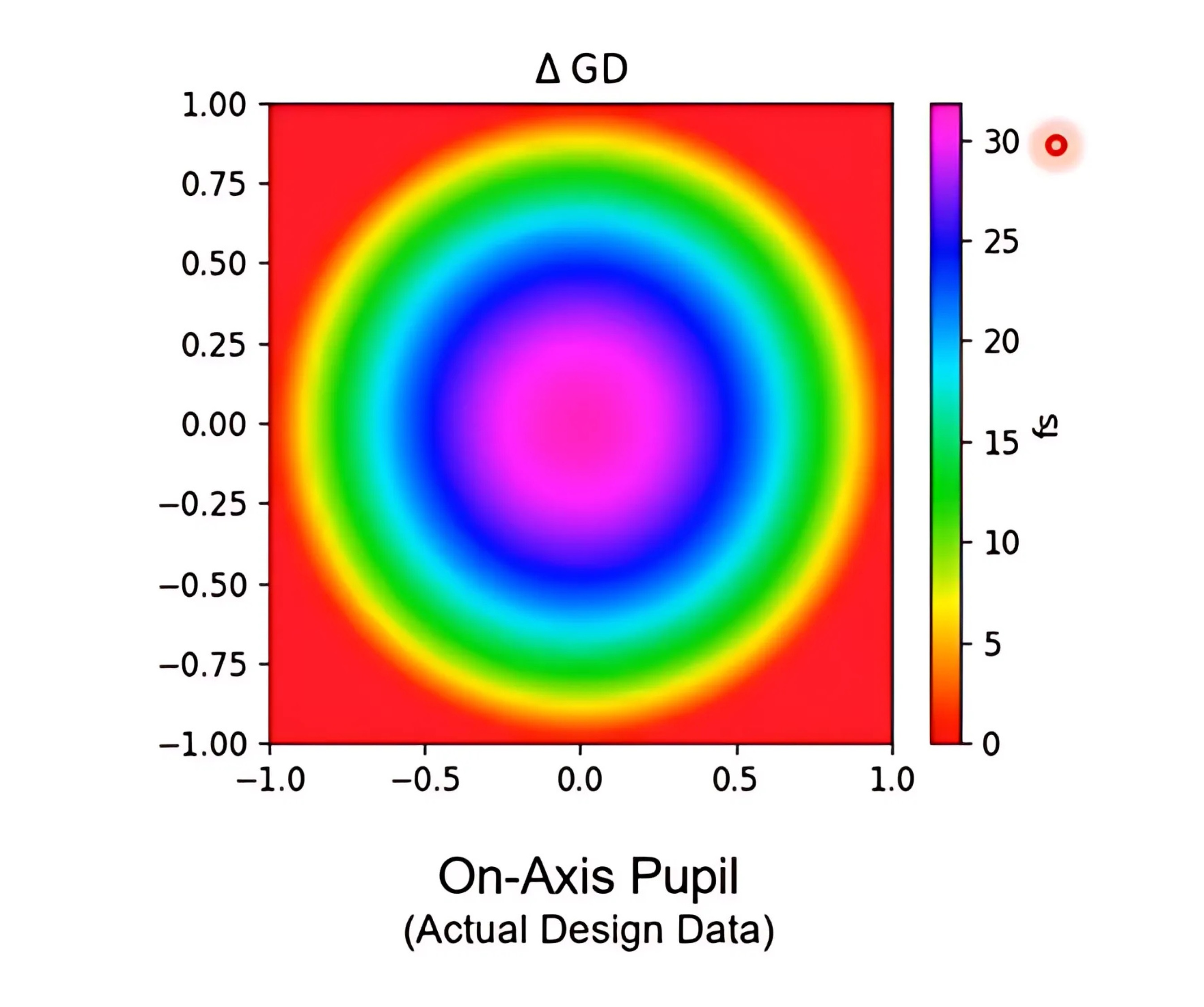
When we plot the Δ GD through an f-theta lens and then vary the field positions like in Figure 10, we see some wild variations crop up:

When we move slightly off-axis, the ΔGD is 60 fs, and at the edge, it magnifies to about 500 femtoseconds. These variations in intensity can lead to extremely high non-uniformity across the entire field. The scan can look a particular way at the center and look completely different at the edges. When we plot the entire field using two f-theta lenses—one with good group delay control and the other with poor control—the difference in uniformity becomes clearly visible.

We see that an f-theta lens with good control only displays a total Δ GD of 24 fs while a poor lens has one as high as 475 fs.
These variations in intensity also mean that the output pulse will be substantially different at the center compared to the edges, leading to a print that is of variable quality throughout the field. Fortunately, if the Δ GD of a lens is known, we can use software to minimize this and create a uniform field.
Group Delay Dispersion Pupil Distortion and Field Uniformity
We observe a similar phenomenon when considering the variation in GDD across the pulse profile. While regular GDD affects ultrafast pulses uniformly, causing consistent temporal broadening throughout the entire beam. GDD pupil distortion creates non-uniform broadening where different spatial regions experience varying amounts of pulse stretching.

For instance, the center of the beam may undergo greater GDD-induced broadening compared to the edges. Like Δ GD variations, this distortion becomes increasingly pronounced as we move from the center of the scan field toward the periphery, as shown in Figure 12.
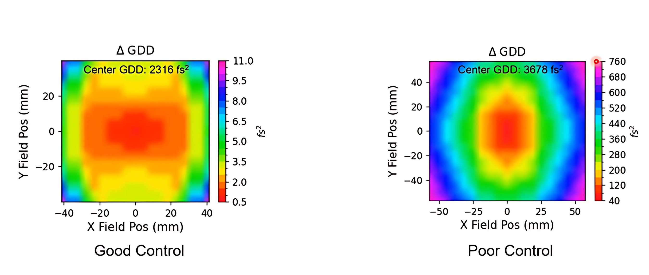
In Figure 13, the system on the left demonstrates excellent uniformity with a center GDD of 2316 fs² and minimal field variations spanning only 0.5 to 11.0 fs². In stark contrast, the system on the right exhibits severe non-uniformity, showing a higher center GDD of 3676 fs² and significant field variations ranging from 40 to 760 fs². This can lead to inconsistent processing throughout the field. These issues are also not possible to pre-compensate for, as they are created by the lens itself.
What Should My Final Pulse Look Like?
The final pulse profile in an ultrafast laser system using f-theta lenses represents a complex interplay of optical aberrations and dispersion effects that collectively distort both spatial and temporal characteristics. While ideal systems aim for a uniform, diffraction-limited spot with minimal temporal broadening, real-world pulses often exhibit degraded quality due to wavefront errors, GDD non-uniformity, and chromatic aberrations. Even with advanced design techniques that individually minimize factors like lateral/axial color errors or field-dependent GDD variations, residual distortions persist as spatially varying pulse front tilts, wavelength-dependent focal shifts, and non-uniform temporal stretching across the beam profile.
Modern lens design addresses this by balancing trade-offs, using multi-material corrections for chromatic effects, optimizing pupil-dependent dispersion, and iterative algorithms to suppress dominant aberrations. Ultimately, the final pulse is a carefully engineered approximation that prioritizes consistency across the scan field over theoretical perfection, ensuring practical usability in applications like micromachining or nonlinear microscopy.
Key Takeaways
- Broadband Sensitivity: Ultrafast laser pulses have wide spectral bandwidths, making them highly susceptible to chromatic aberrations and dispersion effects.
- Limitations of Pre-Chirping: Temporal pre-chirp compensation can address some dispersion but cannot correct chromatic aberrations or spatially varying group delay introduced by the lens.
- Field-Dependent Distortions: Due to their wide scan angles, f-theta lenses are prone to nonuniform group delay (GD) and group delay dispersion (GDD) across the field, causing inconsistent pulse duration and spot intensity.
- Optical Design Solutions: Effective correction requires multi-element, multi-material lens designs to balance chromatic and geometric aberrations, as well as pupil-dependent dispersion.
- Design Optimization: Modern optical design uses specialized algorithms and commercial software to minimize GD and GDD variations directly, targeting each aberration independently.
- Practical Approach: Since it is not feasible to model electric field interaction due to every possible aberration, the best results are achieved by systematically minimizing each independent source of distortion during design.
- End Result: Well-designed f-theta lenses can provide consistent, high-quality focus and pulse characteristics across large scan fields, supporting the precision and reliability needed for advanced ultrafast laser applications.
Color Corrected F-Theta Lenses at Edmund Optics®
The Color Corrected F-Theta Lenses designed and manufactured by Edmund Optics® (Figure 14) integrate multiple cutting-edge fabrication technologies to address key technological challenges in the field while also minimizing the traditional trade-offs associated with them. This breakthrough creates a lens that offers unprecedented versatility for your system. It enables consistent focusing across a wide range of chromatic wavelengths over a broad field. All while delivering an optical solution that maintains uniform scanning geometry and beam quality throughout the entire field. They are diffraction-limited across the scan field, offer low wavefront error, and are ideal for ultrafast scanning applications.

Edmund Optics® also offers a range of f-theta lenses tailored to your needs, including the Sill Optics F-Theta Lenses, designed for Nd:YAG laser scanner systems and ideal for agricultural imaging and confocal microscopy—and the standard Edmund Optics® F-Theta Lenses, which are suited for high-power laser applications due to its high damage threshold and broad input wavelength.
References
- Yurevich, V. I., Grimm, V. A., Afonyushkin, A. A., Yudin, K. V., & Gorny, S. G. (2015). Optical design and performance of F-Θ lenses for high-power and high-precision applications. SPIE Proceedings, 9626, 96261S. https://doi.org/10.1117/12.2190777
- Chen, G. (2023). Design of large working area F-Θ lens [Master's report, University of Arizona]. https://wp.optics.arizona.edu/alumni/wp-content/uploads/sites/113/2023/06/msreport-gong-chen.pdf
- Donald C. O'Shea, "Group velocity dispersion using commercial optical design programs," Appl. Opt. 45, 4740-4746 (2006). https://opg.optica.org/ao/abstract.cfm?URI=ao-45-19-4740
More Resources
- Basics of Ultrafast Lasers
- Ultrafast Dispersion Application Note
- Highly-Dispersive Mirrors Application Note
- Ultrafast Laser Applications: Short Pulse Revolution Webinar Recording
- Choosing the Right Lasers and Optics for Ultrafast Microscopy Webinar Recording
- Ultrafast Optics: Challenges and Solutions Webinar Recording
- Ultrafast Lasers – The Basic Principles of Ultrafast Coherence Application Note
- LIDT for Ultrafast Lasers Application Note
or view regional numbers
QUOTE TOOL
enter stock numbers to begin
Copyright 2023, Edmund Optics Inc., 101 East Gloucester Pike, Barrington, NJ 08007-1380 USA
California Consumer Privacy Acts (CCPA): Do Not Sell or Share My Personal Information
California Transparency in Supply Chains Act
The FUTURE Depends On Optics®