


Optical Coherence Tomography
Authors: Rebecca Charboneau
Optical coherence tomography (OCT) is a noninvasive, high-resolution optical imaging technology that creates cross-sectional images from interference signals received from an object under investigation and a local reference. OCT is commonly used in the medical field for disease diagnosis and treatment monitoring to obtain real-time images of specific organs for direct visualization of tissue structures. OCT systems have axial depth resolutions in the range of 5-10µm, providing an in vivo ‘optical biopsy’ of biological tissues (Figure 1).1 Compared to confocal microscopy , OCT can resolve images with 100 times better axial resolution and also provides a label-free method for in vivo diagnosis.2 While a variety of light sources can be used, using a broadband light source for OCT can provide a cost-effective option for system development as well as a safe energy level for use with biological tissues.
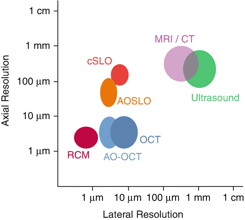
Figure 1: Optical imaging resolution comparison1
How it Works
The principal idea of OCT is that depth information is encoded in light that reflects from a sample. The depth information can be extracted via OCT in any of several methods. The methods fall into one of two broad categories to be described below. A Michelson type interferometer is utilized as the basis of any OCT system (Figure 2). The first implementation of OCT was called Time Domain OCT (TD-OCT). The fundamentals of TD-OCT rely on light from a broadband light source being split into two paths by a beamsplitter. After passing through the beamsplitter, one beam is directed to the sample and the other to a mobile reference mirror. The light from the reference arm will travel a specific optical distance as it moves, and because of the low coherence length of the source, will form an interference pattern only with light that travels the same optical distance in the sample arm. The intensity of the interference as the mirror moves provides a map of the depth profile (the “A-scan”). By rastering the location of the A-scan, the interference pattern can produce two-dimensional (2D) and three-dimensional (3D) images of tissues in the body.
Fourier domain OCT (FD-OCT) is another method of extracting a depth profile from interference generated in a Michelson interferometer. Like time-domain OCT, it utilizes reflection from a reference mirror and reflection from the sample, but in this case the reference mirror is stationary. The spectrum of the recombined light is acquired by, for example, using a grating to spread the spectrum onto an array detector. The depth information is coded in the spectrum of the interference signal. Once spectral information is collected from the interferometric signal, the A-scan (depth profile) is computed via Fourier transformation to yield high resolution images.
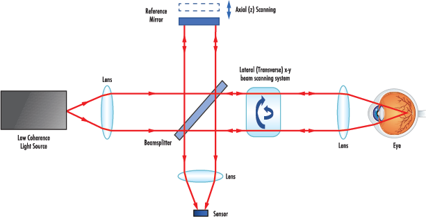
Figure 2: TD-OCT optical diagram
In the years since OCT was first introduced, many enhancements have been developed. The effort to improve the technique continues to this day. One particularly promising enhancement is the use of adaptive optics to improve the clarity of OCT images. Adaptive optics OCT (AO-OCT), as seen in Figure 1, improves system performance by utilizing adaptive technology that corrects the optical wavefront3. For example, a deformable mirror is used in place of a standard optical mirror in an AO-OCT system to reduce present aberrations and yield a higher axial resolution on the order of 2-5µm3.
Optical Path Description
An OCT system can be constructed from discrete optical components as described below, or from their fiber optic equivalents.
- Light Source: according to the classic principle of OCT, a broadband light source with a short coherence length is used for imaging. The short coherent length of the emitted light determines the axial resolution for OCT imaging. However, alternative sources, such as a wavelength-swept laser, can be used to optimize the frequency-dependent reflectance of a given sample for better image quality than that possible using TD-OCT. Specific wavelength ranges, such as visible or infrared light, can also be used to reduce light scattering depending on the sample. Selecting the proper light source based on the sample can optimize the performance of the OCT system.
- Beamsplitters: plate or cube beamsplitters can be used in OCT to split the light into two different paths: the reference and sample beams. The beamsplitter allows for the reference beam to be reflected to the reference mirror while the sample beam is focused into the sample using an optical lens.
- Dielectric Optical Mirrors: this mirror is used to reflect the reference beam to a known path length back into the interference system. The mounted reference mirror in a TD-OCT system will have a controlled translation to allow for axial scanning of the sample. The mirror is stationary in FD-OCT. These mirrors feature a dielectric coating that is ideal for reflection applications as the mirrors feature greater than 99% reflection.
- Optical Lens: a standard plano-convex (PCX) can be used to focus the split beam paths into the sample and detector. To reduce potential spherical and chromatic aberrations, an aspheric or achromatic lens can be utilized. These lenses will focus the light into the sample at a smaller spot size with reduced aberrations, making a more precise OCT system.
- Detector: the detector can come in the form of a single photodiode in the case of TD-OCT and some types of FD-OCT, or for conventional FD-OCT a charge-coupled device (CCD) or a CMOS array that is sensitive to the radiation returning from the sample and reference beam.
- Deformable Mirror: specific for AO-OCT applications. A deformable mirror is an adaptive optic used to reduce aberrations and improve image quality for superior resolution. The shape of the mirror is controlled by an outside signal to correct the wavefront for enhanced system performance.
Image Appearance
The output signal recorded by the detector is a depth scan or commonly referred to as an A-scan or 1D scan (Figure 3). The A-scan describes the axial resolution of the system and it is defined by the bandwidth, or coherence length, of the light source. As the bandwidth of the light source decreases, the axial resolution increases, increasing the system’s resolving power. After an A-scan is collected, the light beam moves laterally across the sample to collect B-scans. The B-scan provides cross-sectional structural information that will produce 2D images based on the magnitude, phase, frequency shift, and polarization of the interference light signal4. 3D or volumetric images are formed by collecting multiple A-scans per B-scan and multiple B-scans per 3D volume4. Intensity information collected in the axial and lateral directions allow for 3D images to be formed in post-processing.
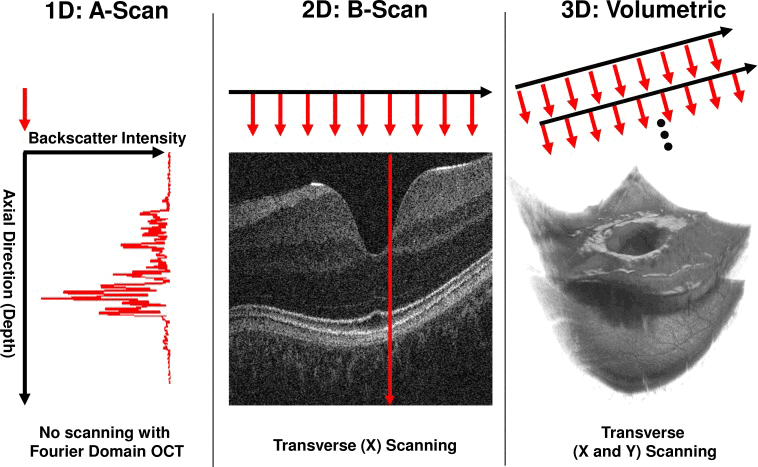
Figure 3: OCT image acquisition5
The image produced from an OCT system can be used to visualize the multi-layer structures in a sample such as the layers of the eye (Figure 4). For example, the image below shows an OCT image of the retina on the right compared to a 2D digital retinal image on the left. The OCT image better defines differences in retinal tissue density with changes in color intensity where, for example, scar tissue build-up could be seen. The color scale produced in the image is a result of the difference in reflectivity of the internal structures of the sample.

Figure 4: OCT retinal images
Applications of OCT
Application 1: Ophthalmology
OCT has allowed clinicians to better diagnose ophthalmic diseases such as age-related macular degeneration (AMD) which causes blurred vision (Figure 5). Two causes of AMD are deterioration of the retina due to tissue thinning (dry AMD) or the formation of leaky blood vessels under the retina (wet AMD).6 OCT technology allows physicians to quantitatively characterize changes in retinal tissue morphology compared to previous procedures that only provide qualitative data.6 For example, OCT can provide images of the retina at a resolution of 5-7µm to track biomarkers like the formation of leaky blood vessels.6 The effectiveness of therapies can also be tracked using OCT by quantifying the retinal thickness and biomarkers to determine if the disease is progressing.
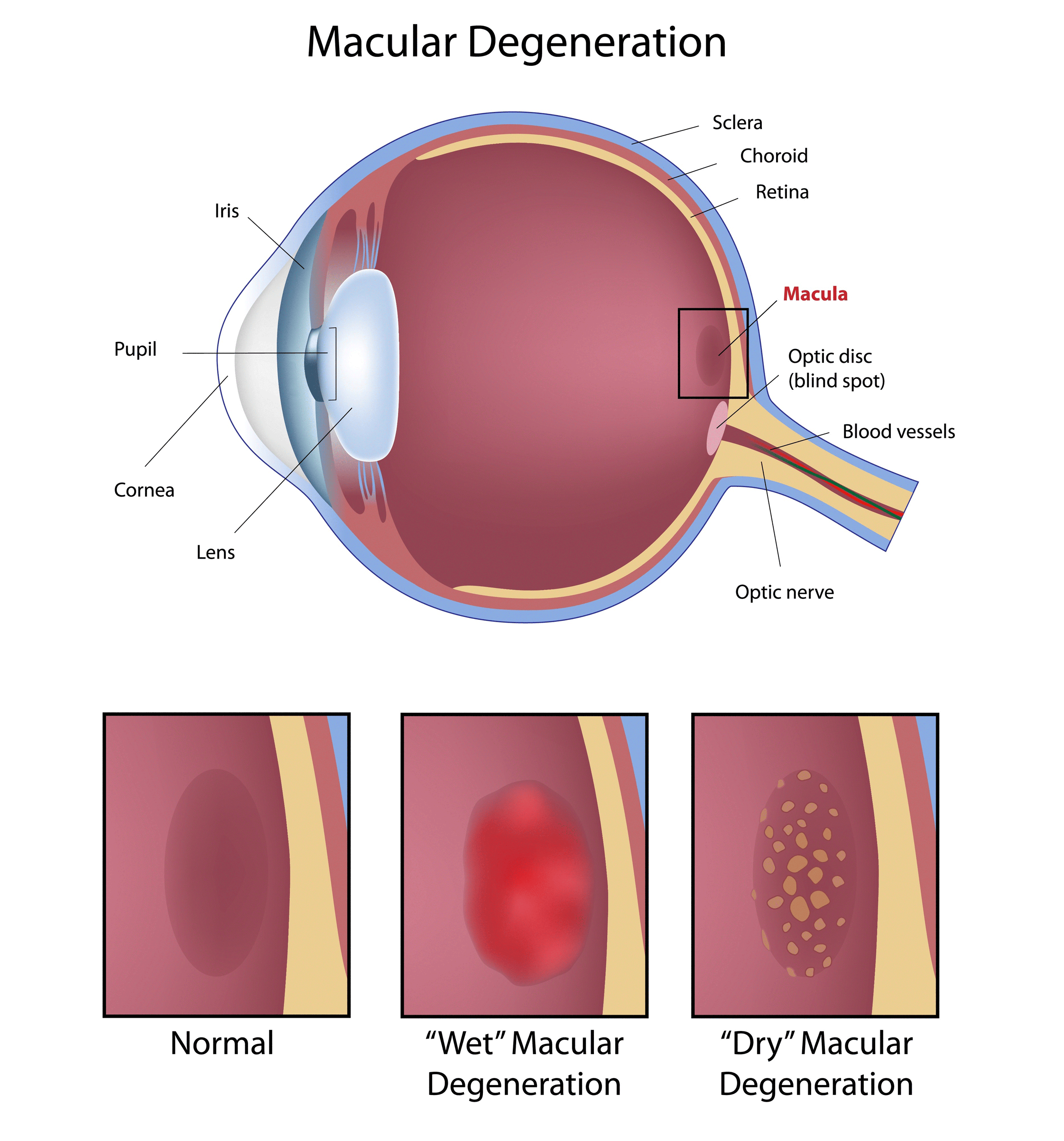
Figure 5: Aged-Related Macular Degeneration
Application 2: Cardiology
Another field that OCT has been adapted for is cardiology to diagnose the likelihood of a heart attack. One of the leading causes for heart attacks is atherosclerosis which occurs when ruptured fatty plaques and calcium build-up inside the lining of the artery wall, blocking blood flow.7 Clinicians have turned to utilizing OCT technologies to detect vulnerable plaques prior to rupture. OCT allows physicians to visualize plaque in the arterial wall with an image resolution of 5-7µm to determine the size, shape, and location of the plaque.8 The high sensitivity of OCT allows better axial penetration to view plaques pre-rupture compared to other diagnostic methods such as angiography and intravascular ultrasound, allowing for early diagnosis.
Optical Coherence Tomography at Edmund Optics®
Edmund Optics® supplies a wide range of optics ideal for OCT systems. As OCT technology advances, Edmund Optics® will continue to expand our product selection and technical support. Noteworthy trends in OCT technology include system portability, accessibility, and miniaturization. Multimodal OCT, which incorporates complementary techniques like microscopy or endoscopy with OCT, AO-OCT, and miniaturized OCT chip-based systems are among the most prevalent future OCT techniques to look out for7. These advanced OCT technologies will continue to drive innovation in the fields of biomedicine, material processing, and other industrial applications where Edmund Optics® will continue to support this application space.

 Visible and NIR Plate Beamsplitter
- Reflectivity ≤1% at 400-700nm or 700-1100nm to reduce back reflections
- Broadband dielectric coatings have minimal energy loss compared to metallic coatings
- 50/50 Reflection/Transmission ratio
- Ideal for low power laser beams
BUY NOW

Broadband Non-polarizing Cube Beamsplitters
- Low Polarization Dependence: |Ts-Tp|<6%
- 50/50 Reflection/Transmission ratio
- BBAR Coated Faces for Maximum Efficiency
- Minimal absorption loss
BUY NOW

Broadband Dielectric λ/10 Mirrors
- Greater than 99% reflection over broad wavelength ranges
- Minimal energy loss ideal for beam steering
- Highly durable fused silica substrate
BUY NOW
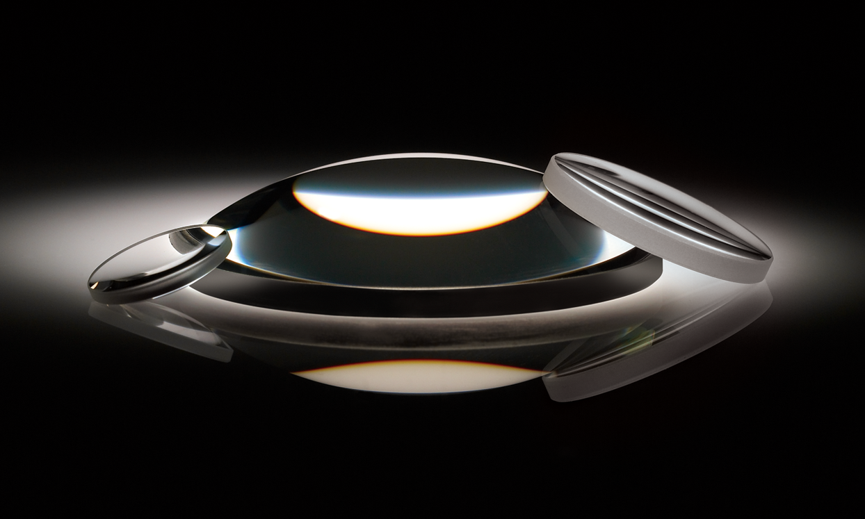
Plano-Convex (PCX) Lenses
- AR coating options available to provide <0.5% reflectance over a wavelength range
- Designed for 0° angle of incidence
- Ideal for light collection and focusing applications
BUY NOW
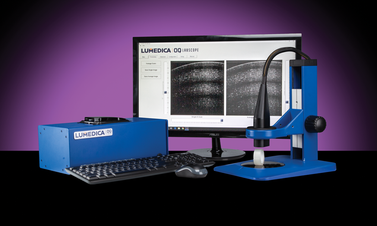
Lumedica OCT Imaging System
- Affordable Optical Coherence Tomography Imaging System
- Ideal for Biological Sample Imaging, Sample Characterization, and OCT Education
- Compact design for benchtop
BUY NOW
References
- Silke Aumann, Sabine Donner, Jörg Fischer, & Frank Müller. (2019, August 14). Optical Coherence Tomography (OCT): Principle and Technical Realization. High Resolution Imaging Microscopy and Ophthalmology, 59-85.
- Dan P. Popescu, et al. (2011, September). Optical Coherence Tomography: Fundamental Principles, Instrumental Designs and Biomedical Applications. Biophysical Reviews, 3(3): 155.
- Michael Pircher and Robert J Zawadzki. (2017, May 1). Review of adaptive optics OCT (AO-OCT): principles and applications for retinal imaging. Biomedical Optics Express, 8(5): 2536-2562.
- Michelle Gabriele, et al. (2010, June 11). Three Dimensional Optical Coherence Tomography Imaging: Advantages and Advances. Progress in Retinal Eye Research, 29(6): 556-579.
- Martin Kraus, Markus Mayer. (2012, June). Motion correction in optical coherence tomography volumes on a per A-scan basis using orthogonal scan patterns. Biomedical Optics Express, 3(6): 1182-1189.
- Alfredo Garcia-Layana, Gianfranco Cuiffo, Javier Zarranz-Ventura, Aurora Alvarez-Vidal. (2017, July). Optical Coherence Tomography in Age-Related Macular Degeneration. AMD Book.
- Mitsuyasu Terahima, Hideaki Kaneda, & Takahiko Suzuki. (2012, February 28). The Role of Optical Coherence Tomography in Coronary Intervention. Korean Journal of Internal Medicine, 27(1): 1-12.
- Renae Keep. (2021, October 20). Bright prospects for OCT at 30. SPIE Publications.
Additional Resources
- The Ultimate Guide to Beamsplitters
- All About Diffraction Gratings
- High Reflectivity Mirrors
- Understanding Optical Specifications
- High Reflectivity Mirrors for Laser Applications
- Teaching Principles & Applications of OCT
- Fundamentals of Lasers
- Key Parameters of a Laser System
- Introduction to Adaptive Optics and Deformable Mirrors
cross-sectional
or view regional numbers
QUOTE TOOL
enter stock numbers to begin
Copyright 2023, Edmund Optics Inc., 101 East Gloucester Pike, Barrington, NJ 08007-1380 USA
California Consumer Privacy Acts (CCPA): Do Not Sell or Share My Personal Information
California Transparency in Supply Chains Act
This content may include material that has been generated or modified using artificial intelligence (AI).
The FUTURE Depends On Optics®