


Michelson Interferometer Lab Setup: Assembly and Alignment Guide
What is a Michelson Interferometer?
A Michelson Interferometer is an optical instrument used to measure very small distances, changes in refractive index, or wavelengths of light. It features a simple interferometric design involving a coherent light source, a beamsplitter, and two mirrors. The design first splits the coherent source using the beamsplitter. The two beams travel slightly different distances before reflecting off the mirrors and returning into the beamsplitter, where the two beams recombine. If the difference between the two beams’ path lengths is less than the coherence length of the source, interference fringes will be generated that can be used for precise measurements of the characteristics mentioned above. Because the coherence length of a source can be extremely short, precision components and alignment are crucial.
Build a Michelson Interferometer with Standard Lab Components
This application note outlines a laboratory setup of a Michelson Interferometer using readily available components from Edmund Optics®. Designed as a quick, cost-effective solution, the setup enables the realization of a Michelson Interferometer in virtually any lab environment. All required components can be sourced from a single supplier, simplifying procurement. The lab version of a Michelson Interferometer helps to demonstrate the basic principle of interferometry which is widely used in science and industry.
Michelson Interferometer Parts List
The following table provides a list of all products needed for the setup of your Michelson Interferometer with the respective stock number and quantity:
| Assembly | Products needed for Assembly | Stock Number Edmund Optics | Required Quantity |
|---|---|---|---|
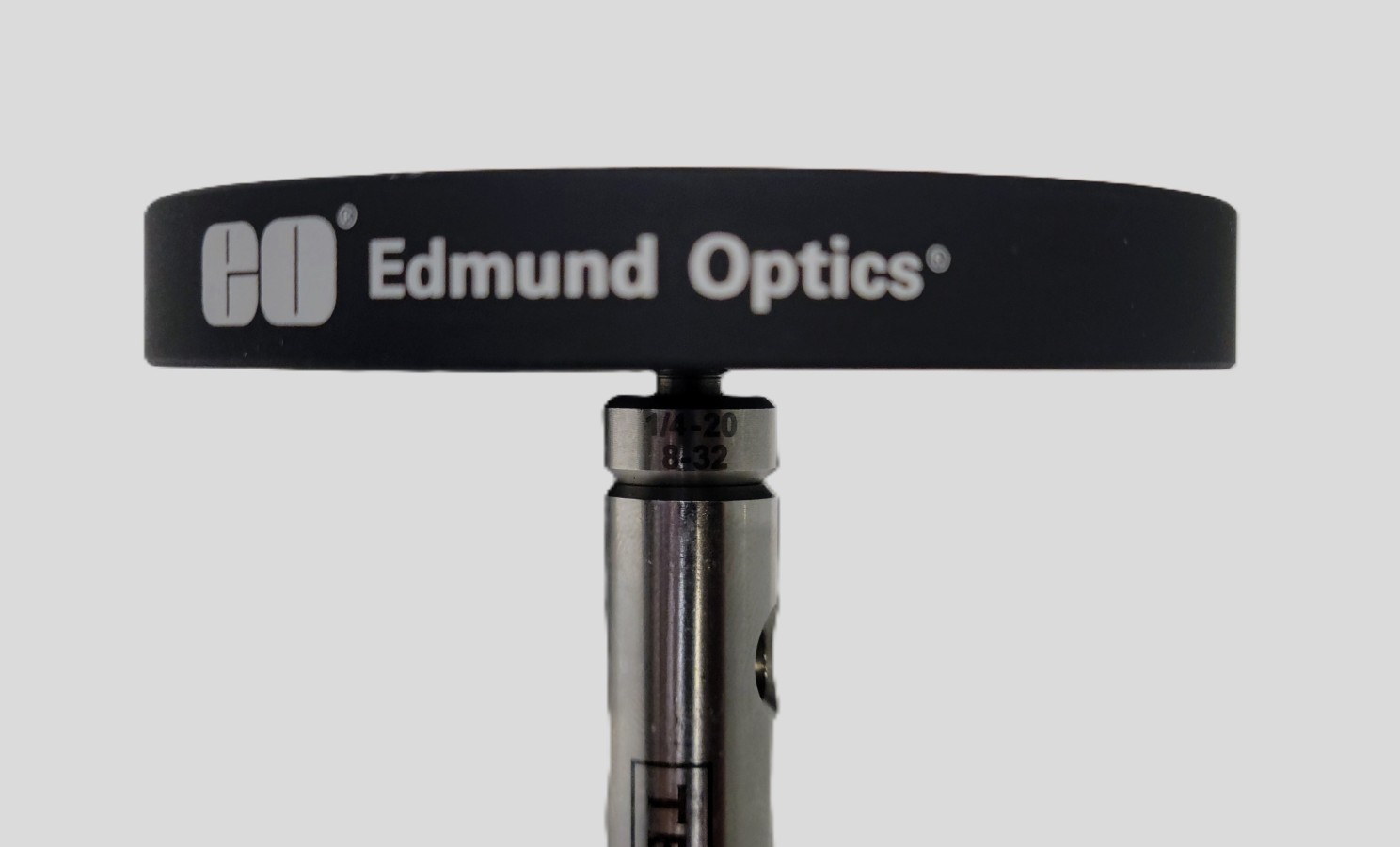
| Optical Base | Compact Optical Rail, 100 mm Length | 54-927 | 5 |
| Breadboard, 300 x 300 mm | 54-638 | 1 | |
| Post Assemblies | Compact Carrier, 15mm Length x 35mm Width | 54-930 | 5 |
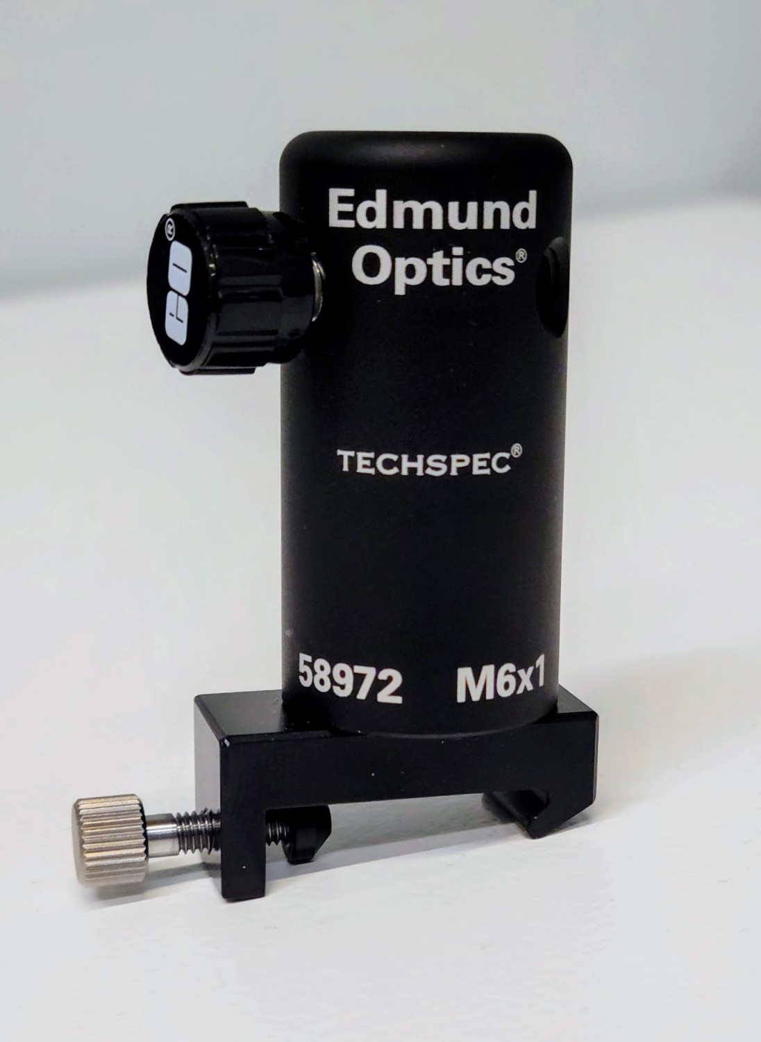
| Post Holder, 50.8mm Length, M6 Thread | 58-972 | 5 | |
| Steel Post, 76.2mm Length, M6 Stud | 59-761 | 5 | |
| Beamsplitter Assembly | Prism Mount | 53-030 | 1 |
| Cube Beamsplitter, 25mm, 50R/50T | 32-505 | 1 | |
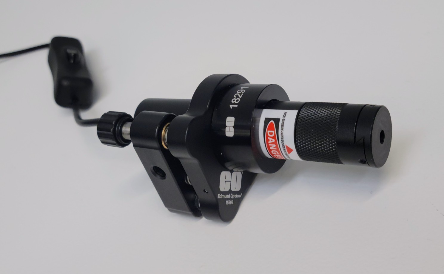
| Laser Assembly | E-Series Kinematic Mount, 25.0/25.4mm Optic Dia. | 15-866 | 1 |
| E-Series, 19.1mm ID Adapter | 18-291 | 1 | |
| Laser 520nm, 10mW or 1mW | 26-938 (10mW) or 72-817 (1mW) | 1 | |
| Mirror Assemblies | E-Series Kinematic Mount, 25.0/25.4mm Optic Dia. | 15-866 | 2 |
| λ/10 Mirror, 25.4mm Diameter, Protected Silver | 39-208 | 2 | |
| Viewer Assembly | SM2 Thin Mount, 50.0/50.8mm Optic Dia. | 17-716 | 1 |
| White Diffusing Glass | 34-475 | 1 | |
| Beam Expander Assembly | SM1 Thin Mount, 25.0/25.4mm Optic Dia., M4 | 13-787 | 1 |
| Plano-Concave (PCV) Lens, 25mm Diameter, -25 FL, VIS 0° Coating | 47-911 | 1 |
Step-by-Step Instructions: Michelson Interferometer Setup for Lab Experiments
Step 1 – The Optical Base
Assemble the Compact Optical Rails with a length of 100 mm onto the Breadboard as shown in Figure 1. The continuous rail portion will be the optical path containing the mirror, beamsplitter, beam expander and viewing target.
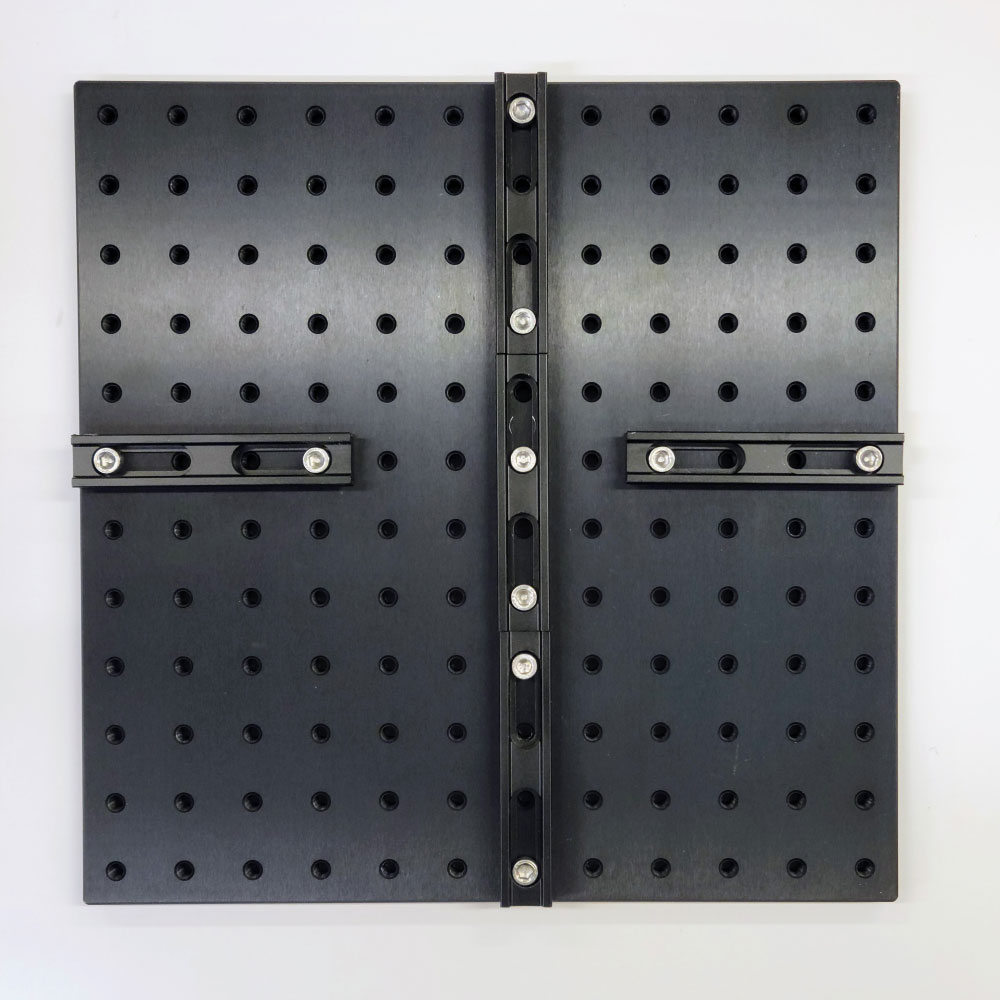
Step 2 – The Post Assemblies
Next, assemble the post holder setups: Mount the five TECHSPEC® Post Holders to the Compact Carriers using Socket Head Cap Screws (M6x1.0) as shown in Figure 2. Figure 3 shows the completed assembly.
Step 3 – The Laser Assembly
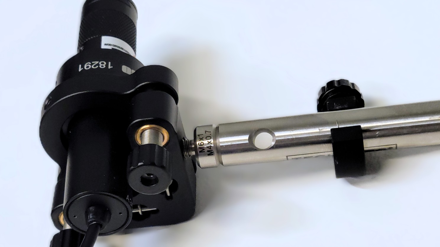
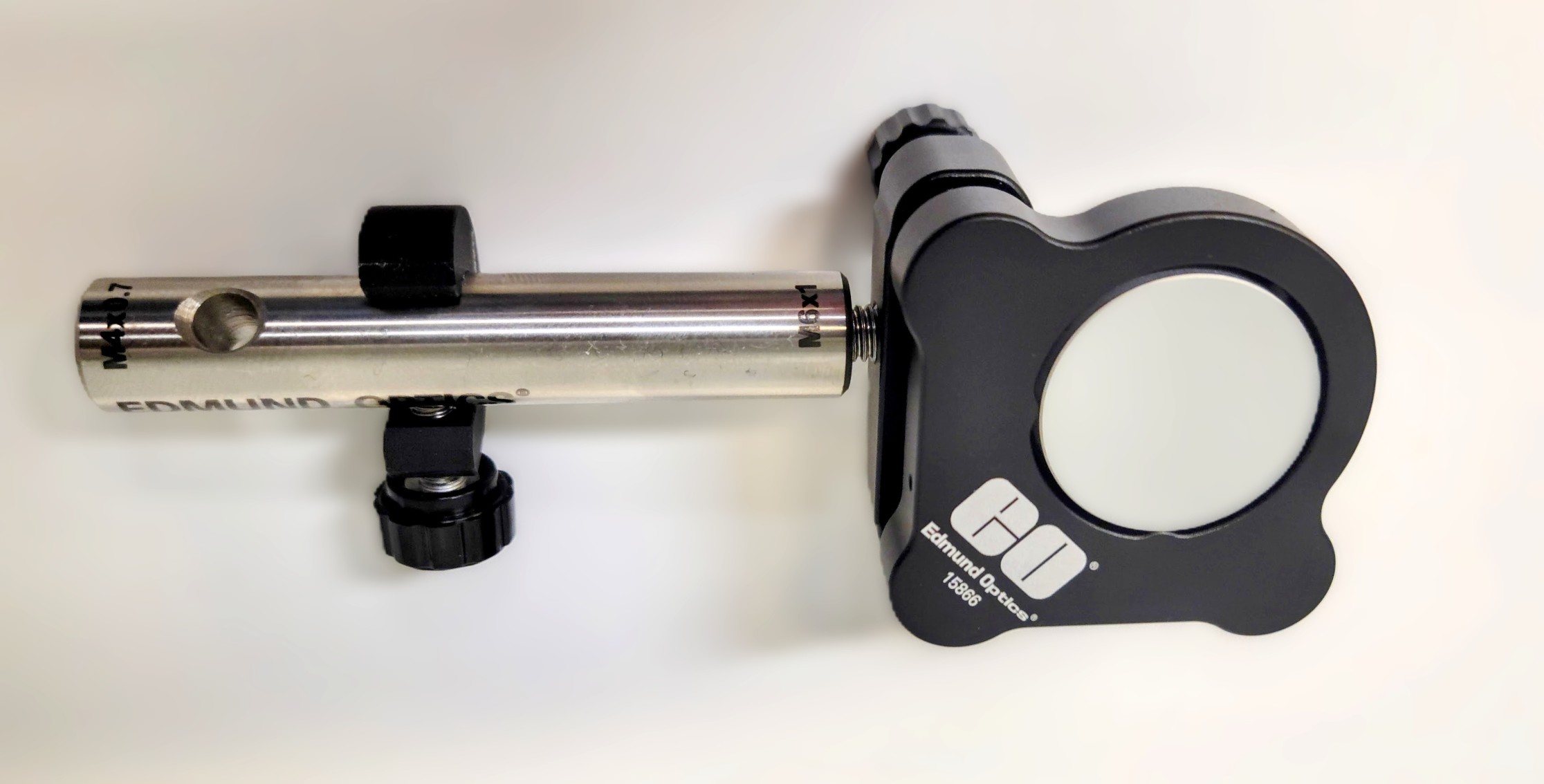
For the laser assembly, mount the E-Series ID Adapter into the E-Series Kinematic Mount and then insert the laser and tighten the set screw, as shown in Figure 4. The laser with stock number 26-938 recommended in the table above is sold as 10mW. For safety reasons, you can use the laser software to reduce the output power to only 1mW. When considering options, you might find that a red diode laser or a comparable low-power laser like stock number 72-817 is also a suitable choice based on availability and budget constraints. It is worth noting that diode lasers possess adequate coherence for educational demonstrations, as you will see in this experiment. Figure 5 shows the laser assembly mounted to a post.
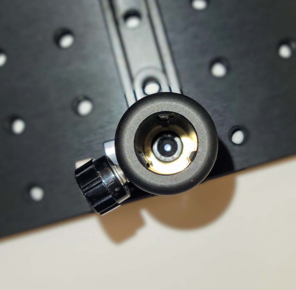
Step 4 – The Mirror Assemblies
For the mirror assemblies, use a set screw to secure the optics in place within the E-Series Kinematic Mount. Secure the posts to the kinematic mounts. You may want to consider using TECHSPEC® Post Collars (stock number 58-992) for quick reassembly as shown in Figure 6.
Step 5 – Mounting the Laser & Mirror Assemblies
Now you can mount the laser assembly and one of the mirror assemblies onto the rails opposite each other as shown in Figure 7.
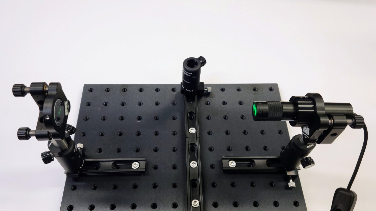
Adjust the screws on the mount to align the mirror and reflect the beam right back to the laser. Try to get the mirror as normal as possible to the laser. In this setup a little bit of back reflection into the diode laser is not too detrimental, because the power of the laser is not very high.
Next, move the first mirror to the continuous rail path. The post collar helps to keep the height constant while aligning the second mirror. Use the laser to repeat the alignment process for the second mirror (see Figure 8).
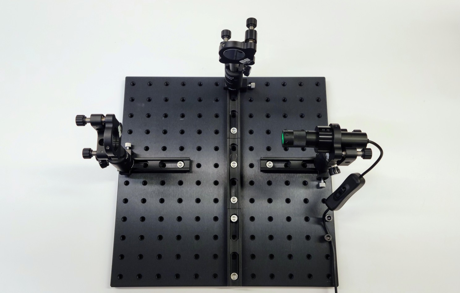
Step 6 – The Beamsplitter Assembly
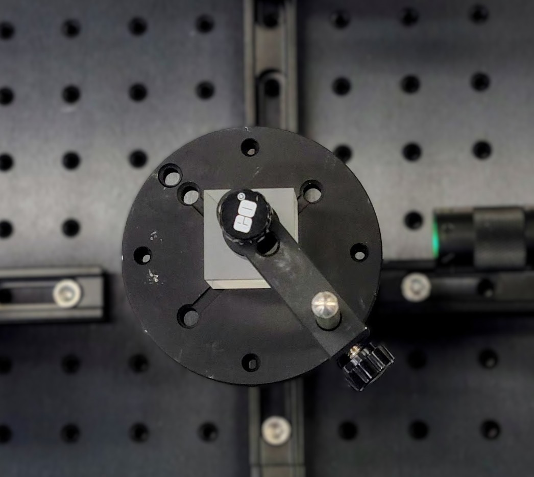
Now you have to assemble the cube beamsplitter mount. The Prism Mount with stock number 53-030 from Edmund Optics® requires a 1/4-20 Thread Adapter in order to be mounted to the post (see Figure 9). Be sure to use Fingercots when handling the TECHSPEC® Beamsplitter Cube to avoid dirt and fingerprints.
The placement of the beamsplitter cube is shown in Figure 10, where we have 50% of the light reflecting off the hypotenuse and onto the first mirror at 90 degrees. Move the top of the beamsplitter mount to the middle of the beamsplitter and carefully tighten down the cube (Figure 11).
Step 7 – The Beam Expander Assembly
Next, assemble the beam expander and the viewer screen (complete assembly shown in Figure 12). Once assembled, place the two carriers and post holders after the beamsplitter and first add the viewer screen. Make sure the two beams are roughly on the screen before placing the expander lens between the beamsplitter and the screen.
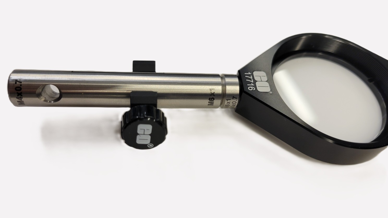
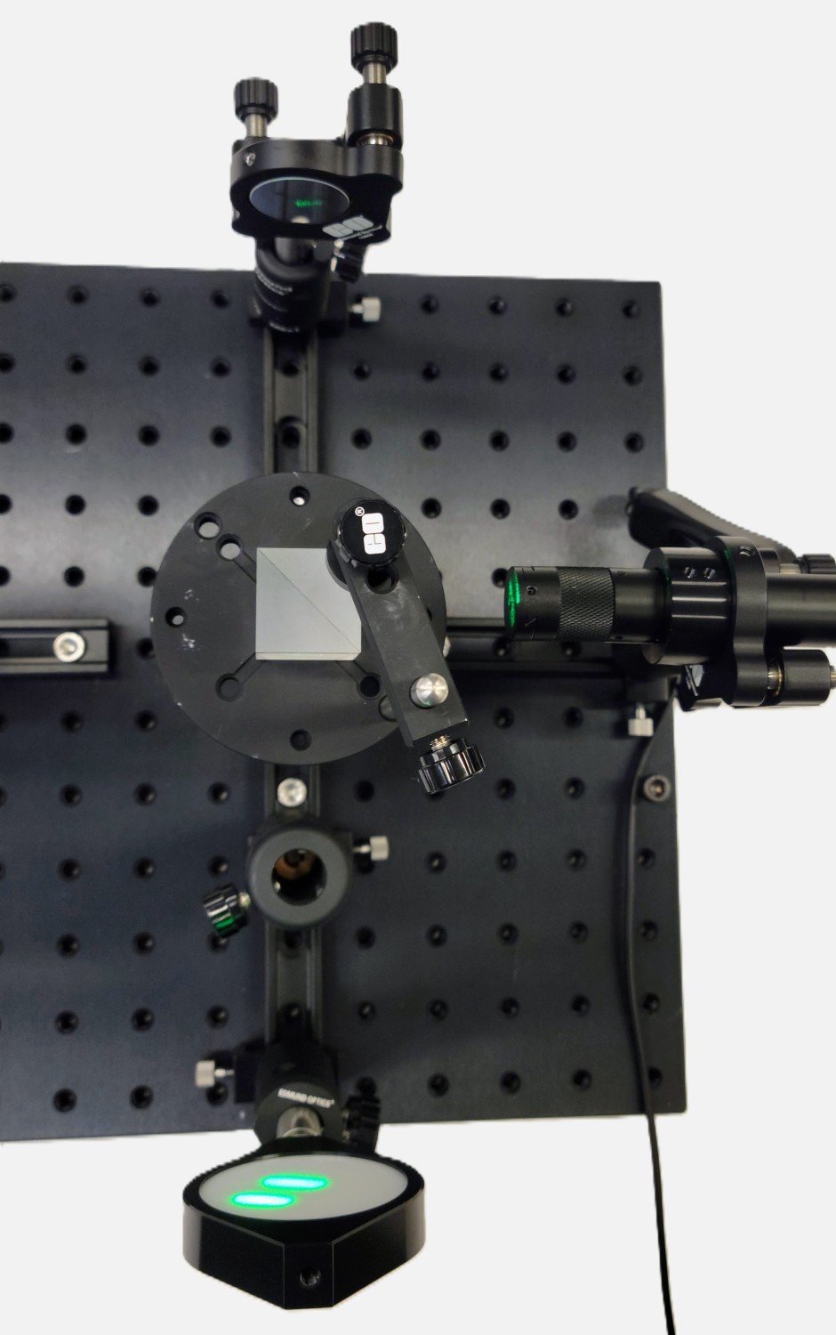
Figure 13 shows the final setup. Adjust the kinematic knobs on the mirrors to align the two beams and see the interference pattern on the viewer screen.
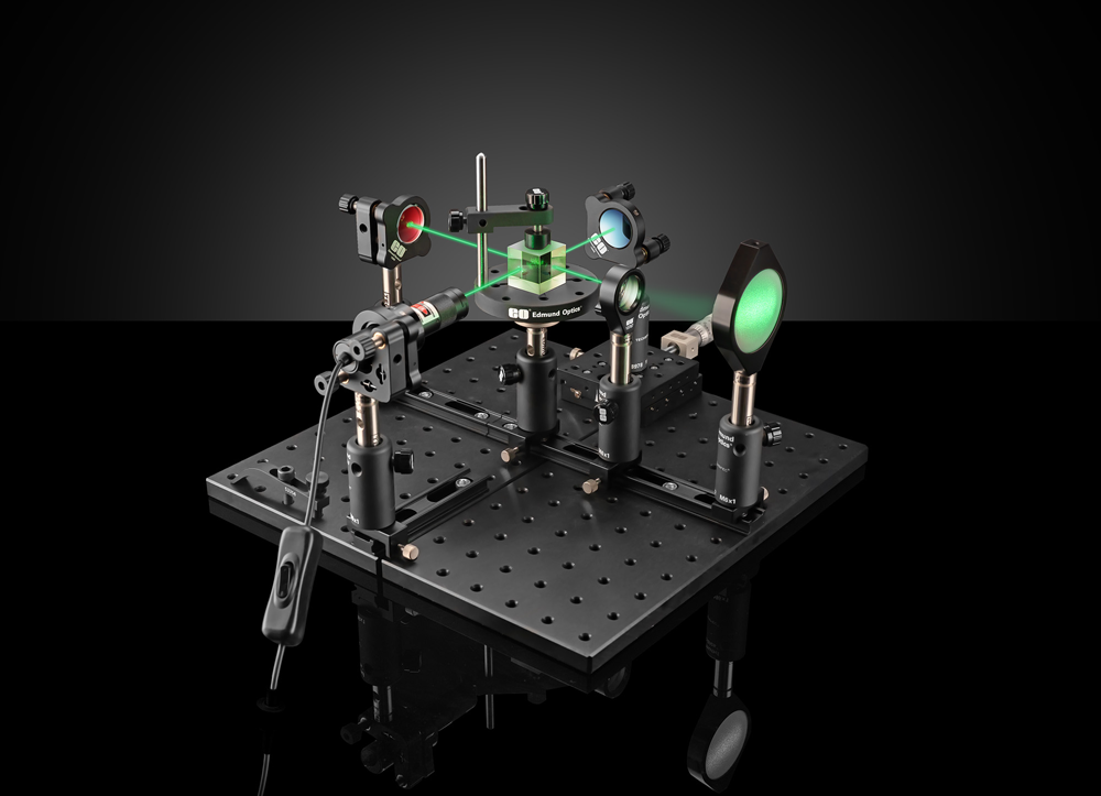
Final Adjustments
When the two mirrors are perfectly aligned such that their surfaces are exactly perpendicular to each other, the optical path differences across the mirror surfaces remain constant. As a result, the observer sees an interference pattern consisting of concentric rings or fringes. When one of the mirrors is moved along the rail, the path length changes, causing the fringes to shift. This shift in the interference pattern can be used to measure changes in optical path length. If a gas cell is inserted into one of the arms, the pattern shift can be analyzed to determine the refractive index of the gas. The refractive indices of other materials can also be measured using similar principles, although the setup and measurement procedures become more complex. For measurement of the wavelength, use the following equation: λ=2⋅Δd / N, where λ is the unknown wavelength, Δd is the mirror displacement and N is the number of observed bright or dark fringes.
If you are looking for more detailed information on interferometry or interferometers please follow the links below this application note. For any questions please contact us!
or view regional numbers
QUOTE TOOL
enter stock numbers to begin
Copyright 2023, Edmund Optics Inc., 101 East Gloucester Pike, Barrington, NJ 08007-1380 USA
California Consumer Privacy Acts (CCPA): Do Not Sell or Share My Personal Information
California Transparency in Supply Chains Act
The FUTURE Depends On Optics®